

C19 Power Cord Guide: C19 vs C20, Ratings, Uses & Selection
Content Menu
● What Are C19 and C20 Connectors?
● C19 vs C20: What's the Difference?
● Where Are C19/C20 Power Cords Used?
● Power Density and C19/C20 Applications
● How to Choose the Right C19/C20 Power Cord
● How to Choose the Right C19 Power Cord Length
● Common Mistakes When Buying C19/C20 Power Cords
● C19/C20 Power Cord Certifications and Compliance
● OEM & Custom C19/C20 Power Cord Solutions
● FAQ
C19 and C20 connectors form part of the IEC 60320 family of appliance couplers and are widely used for higher-current power distribution in data centers, server rooms, rack PDUs and related high-density IT environments. A C19 power cord typically carries the cable-side connector that mates with a C20 inlet on servers, UPS systems or PDUs.
This guide covers the roles of C19 and C20, their relationship to C13/C14, electrical ratings, wire gauge and length considerations, application contexts including power density, selection criteria, common purchasing mistakes, certifications and customization options. It is intended for data center operators, IT procurement teams, PDU and UPS buyers, power cord importers and OEM/ODM customers who need clear technical information for specification and sourcing decisions.
What Are C19 and C20 Connectors?

IEC 60320 defines standardized appliance couplers for connecting equipment to the mains. Within this system, odd-numbered designations generally refer to the cable-side connector, while even-numbered designations refer to the equipment-side inlet.
What Is a C19 Connector?
The C19 is the cable-side (female) connector. It is molded onto one end of a power cord and plugs into a matching C20 inlet. An IEC C19 power cord is commonly specified when the equipment requires a higher-current connection than a standard C13 cord provides.
What Is a C20 Inlet?
The C20 is the equipment-side (male) appliance inlet. It is integrated into servers, UPS units, PDUs or other devices and receives the C19 connector.
| Connector | Position | Typical Role |
|---|---|---|
| C13 | Cable side | Standard power connector |
| C14 | Equipment side | Standard appliance inlet |
| C19 | Cable side | Higher-current connector |
| C20 | Equipment side | Higher-current appliance inlet |
C19 vs C20: What's the Difference?
C19 and C20 are a mating pair, not alternative names for the same part.
C19 is the female connector on the power cord.
C20 is the male inlet on the equipment.
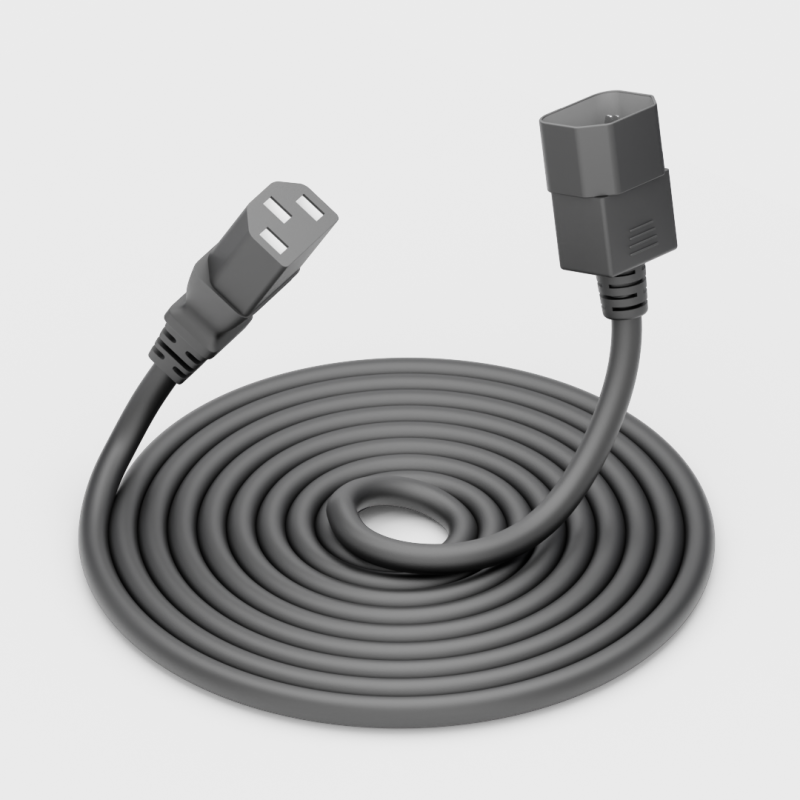
A C19 to C20 power cord is a jumper assembly with C19 on one end and C20 on the other. This configuration is frequently used between a PDU and a server or between a UPS and a PDU. The connectors are not interchangeable in role; the cord end must match the equipment inlet.

C19/C20 Electrical Ratings
Under IEC 60320-1, C19 and C20 connectors are commonly rated for a maximum of 16 A at 250 V AC. Complete cord sets evaluated under North American UL or CSA requirements may carry ratings up to 20 A, depending on wire gauge, plug type and overall construction.
Important distinctions:
- The connector rating under the standard is not identical to the rating of a finished power cord assembly.
- The complete assembly rating is determined by the connector, conductor size, plug, jacket and applicable certification requirements for the target market.
- Final current-carrying capacity also depends on ambient temperature, installation conditions and local electrical codes.
A C19 power cable typically uses three conductors (line, neutral and protective earth). The actual rating of any specific cord must be verified against the equipment nameplate, PDU configuration and destination-market requirements.
C19/C20 vs C13/C14
C13/C14 and C19/C20 belong to the same IEC 60320 family but differ in physical size and typical current capacity.
| Item | C13/C14 | C19/C20 |
|---|---|---|
| Connector position | Cable / equipment | Cable / equipment |
| Typical application | Standard IT equipment | Higher-current IT equipment |
| Physical size | Smaller | Larger |
| Current rating | Typically lower | Typically higher |
| Common applications | PCs, monitors, standard servers | High-density servers, PDUs, UPS |
| Interchangeability | Not interchangeable with C19/C20 | Not interchangeable with C13/C14 |
The larger geometry of the C19/C20 pair prevents direct mating with C13/C14 connectors. This mechanical difference reduces the chance of connecting an under-rated cord to a higher-current inlet. Overall system safety, however, still depends on conductor size, connector and plug ratings, PDU capacity, circuit protection, equipment load and operating temperature.
Where Are C19/C20 Power Cords Used?
C19 and C20 connectors appear most often in environments that require higher current than a standard C13/C14 combination:
1. Rack Servers – Higher-power 1U/2U systems and multi-PSU configurations.
2. High-Density / GPU Servers – AI, HPC and GPU-accelerated platforms with elevated power draw.
3. Data Centers – Rack-level power distribution where density and continuous operation are priorities.
4. Rack PDUs – As input connectors or output receptacles on higher-capacity units.
5. UPS Systems – Links between UPS units and downstream PDUs or critical loads.
6. Networking Equipment – High-end core switches and chassis systems.
Not every server or data-center device uses these connectors. Selection is driven by the equipment inlet, rated current and overall power distribution design.

Power Density and C19/C20 Applications
In high-density IT environments, power density—the amount of power delivered per rack unit or per square meter—often increases the current required at individual inlets. C19/C20 connectors are widely applied in these settings because they support higher continuous current than the C13/C14 pair while remaining compatible with standard rack PDUs and UPS outputs.
Typical contexts include dense server deployments, GPU and AI server racks, and rack-level power distribution where multiple high-draw devices share limited space. The decision to use a C19 power cord for server, data center or PDU applications is based on the specific inlet type, current demand and system design rather than power level alone.
How to Choose the Right C19/C20 Power Cord
Specification should consider the complete cord assembly and the installation environment:
1. Connector configuration – Confirm C19 on the equipment end and the correct mating connector or plug on the supply end.
2. Current rating – Match the complete assembly rating to the equipment and circuit requirements.
3. Voltage – Align with the product rating and target market.
4. Wire gauge / conductor size – Select according to current, length and ambient conditions.
5. Cable length – Balance reach, voltage drop and cable management.
6. Plug type – Choose the appropriate regional plug or C20 connector for jumpers.
7. Jacket material – PVC, LSZH or other compounds based on fire-safety and environmental needs.
8. Certification – Verify approvals required for the destination market.
9. Operating environment – Account for temperature, airflow and installation density.
10. PDU / UPS compatibility – Ensure inlet and outlet types match the intended connection.
| Specification | Typical Options / Considerations |
|---|---|
| Connector | C19 / C20 |
| Voltage | According to product and target market |
| Current | According to complete cord assembly |
| Conductor | Copper |
| Wire Gauge | Project-dependent / customized |
| Cable Length | Standard or custom |
| Plug | Regional configuration |
| Jacket | PVC / LSZH / specified material |
| Certification | Market dependent |
| Application | Server / PDU / UPS / Data Center |
| OEM/ODM | Available |
C19 Power Cord Wire Gauge
Wire gauge (AWG or mm²) directly affects current-carrying capacity, voltage drop and thermal performance. There is no single fixed conductor size that applies to every C19 power cord.
Selection depends on:Rated current of the complete assemblyCable length Ambient temperature Connector and plug ratingsTarget-market certification requirementsOverall system design
Longer runs or higher continuous loads generally require larger conductors to limit voltage drop and temperature rise. Copper is the standard conductor material. The final gauge must be consistent with the lowest-rated component in the assembly and with applicable electrical codes. Typical project examples vary; the correct size is determined case by case rather than by a universal rule.
How to Choose the Right C19 Power Cable Length
Cable length should be chosen to suit the physical layout while avoiding excess slack or excessive voltage drop. Factors include:Relative positions of the PDU and the server or other equipmentRack layout and cable routing pathsCable management and airflow requirementsInstallation constraints
Common standard lengths such as 0.5 m, 1 m, 1.5 m and 2 m are widely available. Custom lengths can be produced to match specific rack configurations. The goal is a length that provides reliable connection without unnecessary bulk or measurable voltage drop under the expected load.
Common Mistakes When Buying C19/C20 Power Cords
Frequent issues observed in procurement include:
1. Checking only the connector type and overlooking the rating of the finished assembly.
2. Selecting an inadequate conductor size for the continuous load and length.
3. Ignoring the combined ratings of plug, connectors and cable.
4. Overlooking regional certification requirements.
5. Choosing an incompatible plug or PDU configuration that complicates installation.
Addressing these points early reduces the risk of thermal issues, non-compliance or field problems.
C19/C20 Power Cord Certifications and Compliance
IEC 60320 defines the dimensional and performance requirements for the connectors. Finished power cord assemblies are evaluated under additional standards according to the market:
- IEC-related requirements for the coupler
- UL or CSA listings for North American applications where applicable
- VDE or other European approvals where required
- RoHS and REACH material compliance
- Country-specific electrical safety marks
Connector standard compliance and finished-product certification are distinct. Documentation should be confirmed for the specific cord and target market.
Manufacturer Insight
Reliable performance of a C19 power cord depends on consistent control across several production stages:
- Verification that the selected conductor size matches the intended current, length and environmental conditions
- Connector quality, including contact integrity and mechanical retention
- Insulation and jacket materials suited to the operating environment
- Termination quality that maintains electrical continuity under thermal and mechanical stress
- Electrical testing of the finished assembly, which may include continuity, polarity and dielectric withstand (hipot) testing according to the product specification and applicable requirements
- Visual and dimensional inspection of the completed cord
- Alignment of the finished product with the certification requirements of the destination market
These checks are applied according to the product specification and project requirements rather than as a fixed checklist independent of the application.
OEM & Custom C19/C20 Power Cord Solutions
Many projects require more than catalog lengths and configurations. Customization options include:
- Cable length matched to rack layout
- Conductor size selected for current and voltage-drop requirements
- Regional plug types or C19-to-C20 jumper configurations
- Jacket material (PVC, LSZH or other specified compounds)
- Cable color for power-path identification
- Printed or molded markings and labeling
- Packaging suited to volume shipments
- Support for required certifications
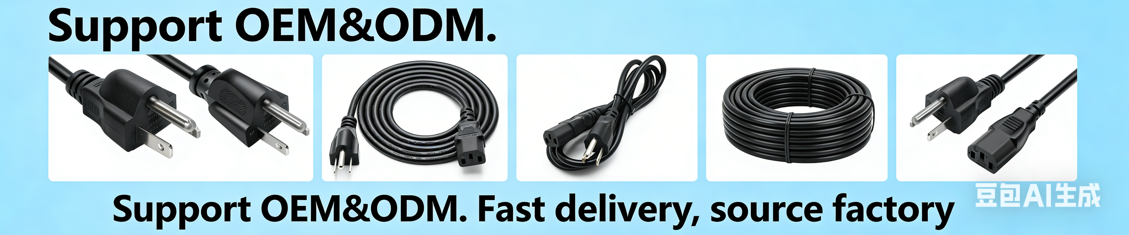
TISDLIP manufactures C19 power cords and related IEC assemblies as an OEM/ODM partner. Engineering support is available to align the cord specification with the customer's equipment, PDU, UPS, destination market and project requirements. The focus is on matching the complete assembly to the electrical and mechanical needs of the installation.
FAQ
Is C19 the same as C20?
No. C19 is the cable-side female connector; C20 is the equipment-side male inlet. They form a mating pair.
What is the difference between C19 and C13?
C19 is larger and typically used for higher-current applications. C13 is the smaller standard connector used on lower-current IT equipment. The two are not interchangeable.
What is the difference between C20 and C14?
C20 is the higher-current equipment inlet that mates with C19. C14 is the standard inlet that mates with C13. They differ in size and current rating and cannot be interchanged.
What is a C19 to C20 power cord?
It is a jumper cord with a C19 connector on one end and a C20 connector on the other, commonly used between PDUs and high-current equipment or between UPS units and PDUs.
What equipment uses C19 power cords?
Higher-current servers, blade enclosures, rack PDUs, UPS systems and certain networking or industrial equipment that features C20 inlets.
What current rating does a C19 power cord support?
Under IEC 60320 the connectors are commonly rated up to 16 A. The complete cord assembly rating depends on wire gauge, construction and applicable certifications and must be verified for the specific product and market.
Can I use a C19 power cord with a C14 inlet?
No. The mechanical structures differ; a C19 connector will not mate with a C14 inlet. The cord connector must match the equipment inlet.
How do I choose between a C13 and C19 power cord?
Base the decision on the equipment inlet type, rated current, PDU configuration, complete cord assembly rating and applicable standards. Higher power alone does not automatically require a C19 cord.
Can C19/C20 power cords be customized?
Yes. Length, conductor size, plug type, jacket material, color, marking and certification support can be tailored to project requirements.
What certifications are available?
Certifications depend on the target market and may include IEC-related evaluations, UL/CSA, VDE and material compliance marks such as RoHS and REACH. Specific approvals should be confirmed for each product.
Conclusion
C19 and C20 connectors provide a higher-current option within the IEC 60320 family for data centers, servers, PDUs and UPS systems. The C19 is the cable-side connector; the C20 is the equipment-side inlet. They are selected when the equipment inlet, current demand and system design require them, not simply because a device has elevated power.
Effective specification considers the complete assembly—connector ratings, wire gauge, length, plug type, jacket, certifications and compatibility with PDUs or UPS units—together with the operating environment.
If you are evaluating a standard C19 power cord, a C19 to C20 configuration, custom length or conductor size, regional plug, certification requirements or full OEM/ODM production, provide the following details for a precise quotation:
- Connector configuration (C19, C20 or both)
- Required cable length
- Preferred wire gauge or current rating
- Plug type or regional standard
- Target market and required certifications
- Estimated quantity
TISDLIP can review the specification against the equipment, PDU and installation conditions and supply a matching power cord assembly.



 Email
Email