


Content Menu
● 1. Mechanical Factors Causing Adjacent Plug Interference on Multi-Gang Power Strips
● 2. Regulatory Analysis: Scope and Compatibility Requirements Under BS 1363 Standards
● 3. Engineering Evaluation Protocols for Socket Spacing and Plug Clearance
● 4. Controlling Injection Molding Shrinkage and Housing Tolerances
● 5. Practical Engineering Verification Checklist for Product Development
● 6. OEM and ODM Custom Manufacturing Considerations for International Markets
● 7. Frequently Asked Questions (FAQ)
● 8. References and Source Standards
>> Product Customization & Technical Consultation
In multi-gang UK power strip product development, passing fundamental electrical safety tests—such as temperature rise, insulation resistance, dielectric strength, and shutter operation—is only part of ensuring commercial viability and compliance. Engineering teams frequently encounter mechanical layout issues during late-stage prototyping or third-party laboratory evaluations: adjacent BS 1363 plugs failing to insert simultaneously due to physical housing overlap and insufficient clearance.
While socket pitch (center-to-center distance) serves as a baseline parameter during initial CAD drafting, nominal center distance alone does not guarantee real-world plug compatibility across diverse market enclosure geometries. Structural factors such as raised perimeter borders, decorative faceplate bevels, housing fillets, and enclosure draft angles can silently restrict spatial allowance, leading to mechanical binding or misaligned pin insertion.

This comprehensive technical guide analyzes the underlying mechanical causes of plug housing interference on UK extension leads, clarifies the regulatory scope under BS 1363 standards, evaluates dimensional tolerances during plastic manufacturing, and provides a structured engineering verification checklist for B2B OEM/ODM manufacturing projects.

1. Mechanical Factors Causing Adjacent Plug Interference on Multi-Gang Power Strips
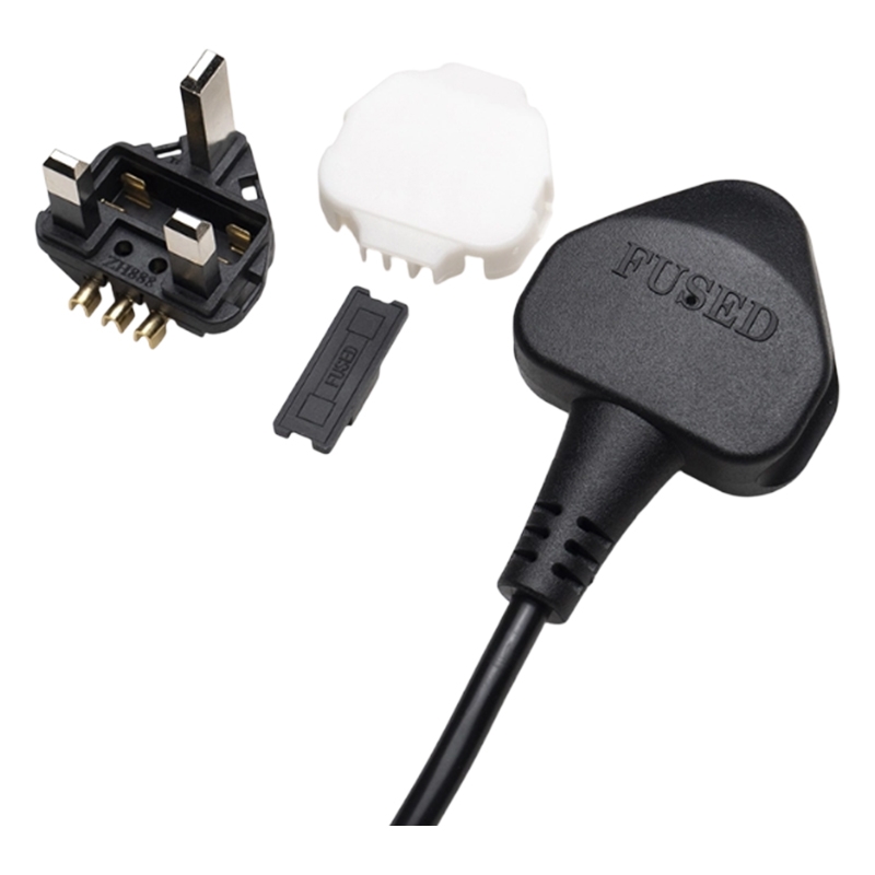
A standard BS 1363 13 A plug features a fixed rectangular pin geometry, but the external molded body profiles vary considerably across appliance manufacturers, strain relief orientations, and integrated electronic assemblies (such as fused bodies, smart meters, or wall adapters). Mechanical interference between adjacent outlets on a multi-gang UK power strip typically stems from a combination of structural layout variables.
1.1 Plug Body Boundary Profile Variations
While the standard defines boundary envelopes for standard 13 A plugs, commercial power adapters, transformer bricks, and right-angled molded plugs often utilize wider or irregular contours above the engagement faceplate. When two oversized plug housings are inserted side-by-side, their physical lateral projections collide before the pins can achieve full insertion depth.
1.2 Center Distance vs. Effective Spatial Clearance
Nominal socket spacing measured from the earth pin center to the adjacent earth pin center may match initial CAD drawings. However, effective spatial clearance is determined by subtracting half of each plug body outer width from the nominal center pitch. If the combined body widths exceed the center distance, mechanical overlapping occurs regardless of how precisely the socket contacts are stamped inside the housing.
1.3 Faceplate Surface Obstructions and Decorative Profiles
Peripheral housing design elements—such as raised decorative borders, mold parting lines, aggressive edge chamfers, or recessed rocker switches—can physically intercept the shoulder or strain relief boot of a fully inserted plug body. Even if center spacing is mathematically sufficient, these raised surface features prevent the plug engagement face from sitting flush against the socket outlet.
1.4 End-Outlet Wall and Bezel Boundary Constraints
Outlets positioned at the far ends of a multi-gang power strip housing often face tight structural boundaries. Designer preferences to minimize total product length can result in internal space compression, where adjacent enclosure end-walls or end-cap bezels restrict the clearance required for wider plug shoulders.
1.5 Engineering Rule for Socket Pitch Calculation
To evaluate mechanical compatibility during CAD layout without relying on complex equations, engineers evaluate clearance using a straightforward spatial relationship:
* Nominal Socket Pitch: The linear distance between the center axes of two adjacent sockets must be greater than half the width of the first plug body plus half the width of the second plug body, plus an added safety margin.
* Plug Body Envelope Widths: Measured across the widest lateral projection of two target plug models chosen for evaluation.
* Safety Clearance Margin: Added to account for injection molding draft angles, part assembly tolerances, and ergonomic ease of insertion/removal.
When effective clearance falls below this boundary limit, operators experience mechanical binding, misaligned pin insertion, or total blockage of adjacent socket outlets—rendering multi-gang power strips partially unusable in practical environments.

2. Regulatory Analysis: Scope and Compatibility Requirements Under BS 1363 Standards
Establishing precise verification protocols requires engineering teams to distinguish between mandatory standard requirements, plug boundary dimensions, and practical tooling guidelines. The BS 1363 standard series published by the British Standards Institution (BSI) is divided into distinct parts based on product architecture.
2.1 Scope of BS 1363 Standard Parts
* BS 1363-1:2023: Specifies requirements for rewirable and non-rewirable 13 A fused plugs. It defines mandatory pin dimensions, gauge testing requirements, and maximum body profile envelopes for plug manufacturers.
* BS 1363-2:2023: Specifies requirements for 13 A switched and unswitched socket-outlets, covering fixed installation wall sockets and portable socket-outlets (multi-gang power strips and trailing sockets).
* BS 1363-3:2023 / BS 1363-4:2023: Cover adaptors and fused connection units, respectively.
2.2 Plug Compatibility and Functional Engagement Requirements
Under BS 1363-2:2023, portable socket-outlets must maintain interchangeability and full engagement compatibility with plugs manufactured to BS 1363-1:2023. The standard mandates that socket configurations must allow compliant plugs to engage fully without structural obstruction that prevents complete pin insertion or proper shutter actuation.
2.3 Deconstructing the "55 mm Center Spacing Rule"
In UK power strip engineering, 55 mm is frequently referenced as a target socket center distance. It is critical to clarify its regulatory and engineering status:
1. An Industry Engineering Datum: The formal text of BS 1363-2 does not explicitly state a single mandatory numerical pitch value (such as 55 mm) applicable to all multi-gang socket layouts. Compliance is verified through physical engagement tests and functional gauge performance.
2. Empirical Design Best Practice: Based on common plug profile envelopes in the market, a center-to-center pitch of approximately 55 mm serves as a practical empirical reference to ensure adjacent outlets accommodate standard side-by-side 13 A molded plugs without binding.
3. Structure-Dependent Performance: A power strip designed with 55 mm center spacing may still experience physical binding if surrounding enclosure walls or raised decorative ribs protrude into the insertion plane. Conversely, specialized socket arrangements must be evaluated against target plug models and project specifications rather than relying solely on a generic numerical rule.
3. Engineering Evaluation Protocols for Socket Spacing and Plug Clearance
Evaluating mechanical compatibility during product development involves a structured engineering assessment prior to tooling sign-off and third-party laboratory submission.
3.1 Establishing Fixed CAD Reference Axes
Define precise geometric reference axes from earth pin contact centers to internal structural ribs, outer housing wall surfaces, and adjacent outlet centers. Relying on unconstrained exterior molded edges can introduce dimensional errors during drafting.
3.2 Incorporating Representative Plug Envelope Models
Import 3D CAD models of standard BS 1363-1 plug body envelopes and common market transformer profiles into the assembly file. Perform automated CAD collision checks to identify physical overlapping between adjacent plug profiles across all socket positions.
3.3 Verifying Simultaneous Multi-Outlet Insertion
Verify that adjacent outlets provide sufficient clearance for concurrent insertion of target plug combinations without mechanical binding. The evaluation should test side-by-side standard plugs as well as combinations involving oversized transformer adapters on end positions.

3.4 Inspecting Peripheral Boundaries and Raised Features
Confirm that end-cap enclosures, side bezels, integrated rocker switches, and indicator light bezels do not obstruct the required insertion depth plane. Ensure that draft angles on deep-drawn faceplates do not narrow the spatial allowance at the base of the socket face.
3.5 Assessing Full Pin Seating and Shutter Actuation
Ensure that inserted plugs seat flush against the socket faceplate plane. Incomplete seating caused by physical housing contact can prevent line and neutral pins from fully opening the internal insulated shutter opening device (ISOD), leading to contact engagement failure or unsafe arcing risks.
4. Controlling Injection Molding Shrinkage and Housing Tolerances
A CAD model designed for proper clearance can still yield non-compliant finished products if plastic resin thermal behavior and mold tooling parameters are not rigorously controlled.
4.1 Volumetric Resin Shrinkage Along Long Enclosures
Thermoplastic materials selected for power strip enclosures—such as Polycarbonate (PC) or PC/ABS flame-retardant blends—experience volumetric thermal shrinkage upon cooling. Linear shrinkage along long multi-gang faceplate housings directly contracts the center-to-center socket distances relative to the original mold cavity dimensions.
4.2 Tooling Machining Tolerances and Draft Angles
Mold cavity machining tolerances, core pin positioning accuracy, and required wall draft angles alter faceplate surface dimensions relative to internal base structures. Draft angles required for clean part ejection can narrow effective spacing near recessed faceplate borders.
4.3 Differential Thermal Warpage
Non-uniform wall thickness or unbalanced cooling channel distribution across long multi-gang enclosure tools causes thermal distortion, bowing, or twisting along the longitudinal axis, altering nominal pitch measurements across intermediate socket positions.
4.4 Managing Manufacturing Tolerance Chains
A structured tolerance review helps prevent cumulative dimensional errors between initial CAD drawings and mass-produced parts:
1. Nominal CAD Layout: Establishes theoretical center distances and spatial clearance margins on the 3D digital assembly.
2. Tooling Cavity Machining: Accounts for mold tolerance accumulation during CNC or EDM machining of core pins and cavity inserts.
3. Resin Processing Parameters: Controls material thermal shrinkage behavior based on supplier datasheets and injection molding pressure/cooling cycles.
4. Post-Molding Cooling and Assembly: Monitors linear dimensional stability across long multi-gang housings to minimize post-ejection warpage.
5. Quality Assurance First-Article Check: Measures critical dimensions on molded sample parts using Coordinate Measuring Machines (CMM) before tooling sign-off.
To maintain required clearance margins, housing development should incorporate resin shrinkage calculations, mold flow analysis, trial sample dimensional inspections, and necessary tooling adjustments prior to volume production.
5. Practical Engineering Verification Checklist for Product Development
Use this engineering checklist during CAD design reviews and prototype sampling prior to finalizing mass production tooling and submitting units for laboratory compliance testing:
Review Item | Inspection Objective | Evaluation Criteria | Verification Status |
|---|---|---|---|
Datum Axis Definition | Verify center-to-center drawing dimensions against internal contact carrier reference points. | Drawing clearly defines fixed geometric reference axes. | Pass Action Required |
Plug Profile Clearance | Perform CAD interference checks using representative BS 1363 plug profile models. | Zero physical geometry overlap between adjacent plug profiles. | Pass Action Required |
End-Gang Clearance | Check distance from outer pin position to peripheral enclosure end-walls and bezels. | Adequate clearance for target plug shoulders at far-end socket positions. | Pass Action Required |
Surface Feature Clearance | Check faceplate bevels, decorative ribs, and switch housings against plug engagement plane. | Zero physical contact before full plug pin seating against socket faceplate. | Pass Action Required |
First-Article Measurement | Measure actual pitch on initial molded sample parts using calibrated measuring equipment (CMM). | Critical dimensions fall within defined design tolerance limits. | Pass Action Required |
Physical Fit Evaluation | Mechanically insert target plug samples side-by-side into prototype housings. | Plugs insert smoothly, sit flush, and release without mechanical binding. | Pass Action Required |
6. OEM and ODM Custom Manufacturing Considerations for International Markets
Developing custom UK power strips for international brand owners, wholesalers, and electrical appliance manufacturers requires balancing electrical safety compliance, enclosure ergonomics, and mechanical precision. Incorporating integrated features—such as USB Power Delivery (PD) charging modules, surge protection indicators, or heavy-duty extension cables—increases internal component density, making physical layout verification essential.
At Dongguan Zhenghao Electric Co., LTD (TISDLIP), we support global B2B clients through OEM and ODM manufacturing services for AC power cords, UK and European socket inner components, extension leads, and customized power strip assemblies. Our engineering team coordinates with client product managers to review CAD technical drawings, evaluate material flame-retardant specifications, arrange precision mold development, and align sample testing protocols before commencing volume manufacturing.
B2B procurement teams and product engineers can submit custom product drawings, target electrical parameters, or project specifications to evaluate structural feasibility, socket center spacing, and tooling development options.
7. Frequently Asked Questions
Q1: What is a power strip called in the UK market?
In the UK, a multi-outlet power strip fitted with a flexible mains cable is most commonly referred to as an extension lead or multi-way extension lead. The term trailing socket is also widely used in electrical trade and industrial contexts. The most appropriate product designation depends on the unit's physical construction, mounting style, and intended application.
Q2: Is 55 mm socket spacing a mandatory requirement under BS 1363-2?
BS 1363-2:2023 does not explicitly state quot;55 mm" as a universal mandatory numerical requirement in its clause text. However, a center spacing of approximately 55 mm is recognized across the electrical manufacturing industry as a practical engineering reference datum to ensure adjacent outlets accommodate standard BS 1363-1 molded plugs without physical body overlap or binding.
Q3: What is the difference between socket center distance and plug clearance?
Socket center distance (pitch) is the linear measurement between the center axes of two adjacent socket outlet positions. Plug clearance refers to the net physical spatial allowance available for plug outer bodies, taking into account faceplate surface contours, side bezels, integrated rocker switches, and adjacent plug housing profiles.
Q4: Why do adjacent UK plugs sometimes interfere with each other on extension leads?
Physical interference occurs when individual plug outer bodies exceed standard minimal pin boundary dimensions, or when power strip socket spacing is compressed during design without accounting for plug profile variations, peripheral decorative ribs, or enclosure side-wall boundaries.
Q5: How does plastic injection molding shrinkage affect socket dimensional compliance?
Thermoplastic resins experience thermal shrinkage and potential warpage during cooling inside and outside the mold cavity. If mold tooling design and processing parameters do not accurately account for material-specific shrinkage characteristics, final housing dimensions can contract, reducing nominal socket pitch and causing plug misalignment.
8. References and Source Standards
1. British Standards Institution (BSI):
*BS 1363-1:2023 – 13 A plugs, socket-outlets, adaptors and connection units – Part 1: Specification for rewirable and non-rewirable 13 A fused plugs.
Official standard defining plug pin dimensions, gauge testing specifications, and maximum plug profile envelopes.
Source: [BSI Knowledge - BS 1363-1:2023]
2. British Standards Institution (BSI):
*BS 1363-2:2023 – 13 A plugs, socket-outlets, adaptors and connection units – Part 2: Specification for 13 A switched and unswitched socket-outlets.*
Official standard specifying safety, operational, and physical compatibility requirements for fixed and portable socket-outlets.
Source: [BSI Knowledge - BS 1363-2:2023]
3. BSI News & Updates:
*Get plugged in to the changes to the BS 1363 standard series.*
Technical guidance on recent revisions to the BS 1363 standard series covering electrical accessories and portable power products.
Source: [BSI Group - Standard Series Updates]
4. UK Legislation & Consumer Protection:
*The Plugs and Sockets etc. (Safety) Regulations 1994.*
Statutory instrument mandating safety standards and plug compliance for electrical equipment in the UK market.
Source: [UK Legislation - Safety Regulations 1994]
-
Product Customization & Technical Consultation
Ensure your UK power strip products achieve structural compliance, seamless plug compatibility, and reliable mechanical performance before mass production. Contact the TISDLIP engineering team to review technical CAD drawings, discuss custom OEM/ODM specifications, and request prototype evaluation.
* Company: Dongguan Zhenghao Electric Co., LTD (Brand: TISDLIP)
* OEM/ODM Scope: Custom UK Power Strips, Extension Leads, BS 1363 Inner Frame Components, AC Power Cords
* Engineering Inquiries: Submit your product specifications or CAD files to our technical support team for structural layout and tooling review.



 Email
